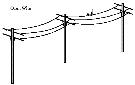
 | |||
The wires in Twisted Pair cabling are twisted together in pairs. Each pair would consist of a wire used for the +ve data signal and a wire used for the -ve data signal. Any noise that appears on 1 wire of the pair would occur on the other wire. Because the wires are opposite polarities, they are 180 degrees out of phase (180 degrees - phasor definition of opposite polarity). When the noise appears on both wires, it cancels or nulls itself out at the receiving end. Twisted Pair cables are most effectively used in systems that use a balanced line method of transmission: polar line coding (Manchester Encoding) as opposed to unipolar line coding (TTL logic).

The degree of reduction in noise interference is determined specifically by the number of turns per foot. Increasing the number of turns per foot reduces the noise interference. To further improve noise rejection, a foil or wire braid shield is woven around the twisted pairs. This "shield" can be woven around individual pairs or around a multi-pair conductor (several pairs).

Cables with a shield are called Shielded Twisted Pair and commonly abbreviated STP. Cables without a shield are called Unshielded Twisted Pair or UTP. Twisting the wires together results in a characteristic impedance for the cable. A typical impedance for UTP is 100 ohm for Ethernet 10BaseT cable.
UTP or Unshielded Twisted Pair cable is used on Ethernet 10BaseT and can also be used with Token Ring. It uses the RJ line of connectors (RJ45, RJ11, etc..)
STP or Shielded Twisted Pair is used with the traditional Token Ring cabling or ICS - IBM Cabling System. It requires a custom connector. IBM STP (Shielded Twisted Pair) has a characteristic impedance of 150 ohms.
| ||
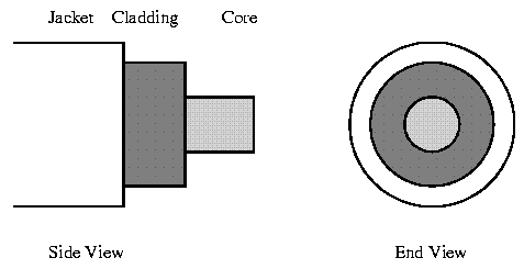 |
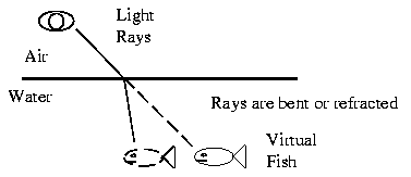
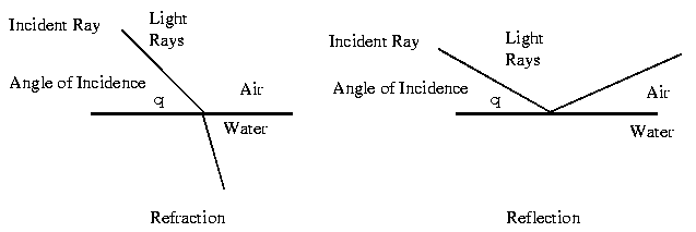
An important characteristic of Fibre Optics is Refraction. Refraction is the characteristic of a material to either pass or reflect light. When light passes through a medium, it "bends" as it passes from one medium to the other. An example of this is when we look into a pond of water. (See image 1 below) If the angle of incidence is small, the light rays are reflected and do not pass into the water. If the angle of incident is great, light passes through the media but is bent or refracted. (See image 2 below) Optical Fibres work on the principle that the core refracts the light and the cladding reflects the light. The core refracts the light and guides the light along its path. The cladding reflects any light back into the core and stops light from escaping through it - it bounds the media! Optical Transmission Modes There are 3 primary types of transmission modes using optical fibre. They are a) Step Index b) Grade Index c) Single Mode |
Transmission Media - UnguidedUnguided Transmission Media is data signals that flow through the air. They are not guided or bound to a channel to follow. They are classified by the type of wave propagation. 16a. RF PropagationThere are 3 types of RF (Radio Frequency) Propagation:
Ground Wave Propagation follows the curvature of the Earth. Ground Waves have carrier frequencies up to 2 MHz. AM radio is an example of Ground Wave Propagation. |

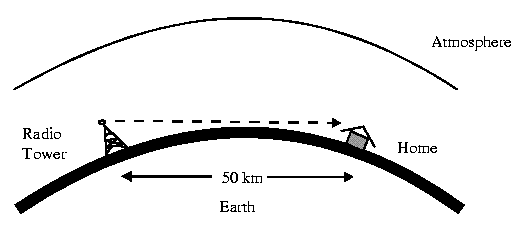
Ionospheric Propagation bounces off of the Earths Ionospheric Layer in the upper atmosphere. It is sometimes called Double Hop Propagation. It operates in the frequency range of 30 - 85 MHz. Because it depends on the Earth's ionosphere, it changes with weather and time of day. The signal bounces off of the ionosphere and back to earth. Ham radios operate in this range. (See image 1 below) Line of Sight Propagation transmits exactly in the line of sight. The receive station must be in the view of the transmit station. It is sometimes called Space Waves or Tropospheric Propagation. It is limited by the curvature of the Earth for ground based stations (100 km: horizon to horizon). Reflected waves can cause problems. Examples of Line of Sight Propagation are: FM Radio, Microwave and Satellite. |
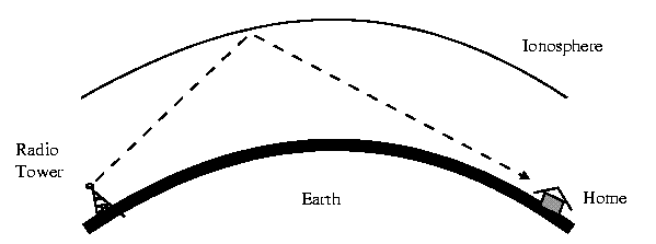
16b. Radio Frequencies
(see table below)
(see table below)
Radio Frequencies are in the range of 300 kHz to 10 GHz. We are seeing an emerging technology called wireless LANs. Some use radio frequencies to connect the workstations together, some use infrared technology.
16c. Microwave
Microwave transmission is line of sight transmission. The Transmit station must be in visible contact with the receive station. This sets a limit on the distance between stations depending on the local geography. Typically the line of sight due to the Earth's curvature is only 50 km to the horizon! Repeater stations must be placed so the data signal can hop, skip and jump across the country.
(see image below)
Satellite
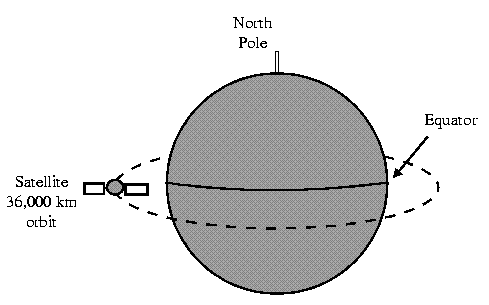
Satellites are transponders that are set in a geostationary orbit directly over the equator. A transponder is a unit that receives on one frequency and retransmits on another. The geostationary orbit is 36,000 km from the Earth's surface. At this point, the gravitational pull of the Earth and the centrifugal force of Earths rotation are balanced and cancel each other out. Centrifugal force is the rotational force placed on the satellite that wants to fling it out to space.


No comments:
Post a Comment